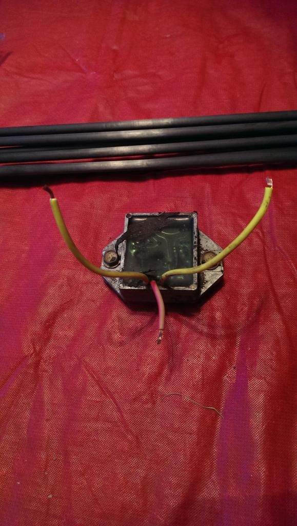
I did an engine swap on a lawn mower not long ago. Now I'm trying to figure out the ignition. The original engine had a "regulator" in the ignition circuit. I have the regulator in front of me. It has 3 wires coming out of it that I'm calling "left", "hot", and "right". See picture.
When I connect my ground probe to the "hot" wire and the hot probe to the left wire and I get 56x ohms of resistance. I do the same to the right wire and I get 54x ohms. No other two wires show resistance so I believe that there are no other ways to make a circuit.
What do these wires do? How do I tell which is power and ground? Of course I could have kept the original engine to find what they do, but its gone. I recall that my tractor has a regulator in the ignition circuit because back in the day coils weren't as good as they are today.
Why don't they teach this chit in schools?